2011年12月3日 星期六

IPsec PPTP L2TP 的差異

穿隧技術 (Tuneling):穿隧技術是為了將私有數據網路的資料在公眾數據網路上傳輸,所發展出來的一種資料包裝方式(Encapsulation),亦即在公眾網路上建立一條秘密通道。現在穿隧技術所使用的協定主要有:IPsec、PPTP 及 L2TP 等三種。
  • IPsec (IP Secruity):為第三層的穿隧技術,專門為 IP 所設計不但符合現有 IPv4 的環境,同時也是 IPv6 的標準,它也是 IEIF 所制定的業界標準,目前 IETF 從 1995 年起,陸續公佈許多網路安全之相關技術標準。這些標準統稱為 IPSec (IP Security),可參考 [RFC 1825]、[RFC 1826]、[RFC 1827]、[RFC 1828]、[RFC 1829]、[RFC 1851]、[RFC 2085]、[RFC 2104]
  • PPTP(Point to Point Tunneling Protocol):定義了一個主從式的架構,主要是由 PNS (PPTP Network Server) 和 PAC (PPTP Access Concentrator) 組成的機制,乃是透過這個機制來支援 VPN 的功能。將 IP、IPX 或 NetBEUI 通訊協定封裝在 IP 封包中,並使用 TCP 方式來交換加密通道的維護訊息。
  • L2TP (Layer 2 Tunneling Protocol):結合 Layer-2 Forwarding (L2F) 和 PPTP 的協定由 IETF 所提出的一個資料連結層的加密通訊協定。
PPTP 與 L2TP 均為第二層的穿隧技術,適合具有 IP/IPX/AppleTalk 等多種協定的環境。IPsec、PPTP、L2TP 三者,最大的不同在於運用 IPsec 的技術,使用者可以同時使用 Internet 與 VPN 的多點傳輸功能 (包括 Internet/Intranet/Extranet/Remote Access...等),而 PPTP 及 L2TP 只能執行點對點 VPN 的功能,無法同時執行 Internet 的應用,使用時較不方便而在安全性方面,IPSec 會對整個傳輸資料做加密而 PPTP 及 L2TP 則是僅針對封包的再包 (Encapsulation) 並未對資料做加密處理,安全性相對較低。

以下引用微軟的文章
通道可將一種通訊協定類型中的封包封裝在另一個通訊協定的資料包中。例如,VPN 使用 PPTP 透過公用網路 (例如,網際網路) 來封裝 IP 封包。可以設定以「點對點通道通訊協定」(PPTP)、「第二層通道通訊協定」(L2TP) 或「安全通訊端通道通訊協定」(SSTP) 為基礎的 VPN 解決方案。
PPTP、L2TP 和 SSTP 高度倚賴一開始指定給「點對點通道通訊協定」(PPTP) 的功能。PPP 是專為透過撥號或專用點對點連線傳送資料所設計。對於 IP,PPP 將 IP 封包封裝於 PPP 框架內,然後透過點對點連結傳輸封裝的 PPP 封包。PPP 一開始定義為在撥號用戶端和網路存取伺服器之間使用的通訊協定。

PPTP

PPTP 允許加密多重通訊協定流量,然後封裝在 IP 標頭裡,以透過 IP 網路或公用 IP 網路 (例如,網際網路) 傳送。PPTP 可用於遠端存取和站對站 VPN 連線。在使用網際網路作為 VPN 的公用網路時,PPTP 伺服器是啟用 PPTP 的 VPN 伺服器,一個介面在網際網路上,而第二個介面在內部網路上。

封裝

PPTP 將 PPP 框架封裝在 IP 資料包中以便透過網路傳輸。PPTP 使用 TCP 連線進行通道管理,並使用 Generic Routing Encapsulation (GRE) 的修改版來封裝通道資料之 PPP 框架。封裝之 PPP 框架的承載可以加密、壓縮,或兩者皆使用。下圖顯示包含 IP 資料包的 PPTP 封包之結構。
包含 IP 資料包的 PPTP 封包之結構
包含 IP 資料包的 PPTP 封包結構

加密

PPP 框架使用 MS-CHAP v2 或 EAP-TLS 驗證程序產生的加密金鑰,來以 Microsoft 點對點加密 (MPPE) 進行加密。虛擬私人網路用戶端必須用 MS-CHAP v2 或 EAP-TLS 驗證通訊協定,才能夠加密 PPP 框架的承載。PPTP 利用基本 PPP 加密,並封裝先前加密的 PPP 框架。

L2TP

L2TP 允許加密多重通訊協定流量,然後透過任何支援點對點資料包傳送的媒體 (例如:IP 或非同步傳輸模式 (ATM)) 來傳送。L2TP 是 PPTP 和「第二層轉送」(L2F) 的組合,這是 Cisco Systems, Inc. 所開發的技術。L2TP 可呈現 PPTP 和 L2F 的最佳功能。
和 PPTP 不同,Microsoft 所執行的 L2TP 不使用 MPPE 來加密 PPP 資料包。L2TP 仰賴「傳輸模式」中的「網際網路通訊協定安全性」(IPsec) 來進行加密服務。L2TP 和 IPsec 的組合即所謂 L2TP/IPsec。
VPN 用戶端和 VPN 伺服器都必須支援 L2TP 和 IPsec。L2TP 的用戶端支援內建於 Windows Vista® 和 Windows XP 遠端存取用戶端,而 L2TP 的 VPN 伺服器支援內建於 Windows Server® 2008 和 Windows Server 2003 家族的成員中。
L2TP 是使用 TCP/IP 通訊協定來安裝。

封裝

L2TP/IPsec 封包的封裝包含兩個層級:
第一層:L2TP 封裝
將 PPP 框架 (IP 資料包) 包裝於 L2TP 標頭和 UDP 標頭。
包含 IP 資料包的 L2TP 封包之結構
包含 IP 資料包的 L2TP 封包結構
第二層:IPsec 封裝
然後將結果 L2TP 訊息包裝在 IPsec「封裝安全承載」(ESP) 標頭和尾端、提供訊息完整性及驗證的 IPsec 驗證尾端,然後是最終 IP 標頭。在 IP 標頭中的是對應到 VPN 用戶端和 VPN 伺服器的來源及目的地 IP 位址。
以 IPsec ESP 加密 L2TP 流量
使用 IPsec ESP 加密 L2TP 流量

加密

L2TP 訊息可使用「網際網路金鑰交換」(IKE) 交涉處理產生的加密金鑰,以「資料加密標準」(DES) 或「三重資料加密標準」(3DES) 進行加密。

SSTP

「安全通訊端通道通訊協定」(SSTP) 是新的通道通訊協定,透過 TCP 通訊埠 443 使用 HTTPS 通訊協定,將流量傳遞通過可能會封鎖 PPTP 和 L2TP/IPsec 流量的防火牆和網路 Proxy。SSTP 提供透過 HTTPS 通訊協定的「安全通訊端層」(SSL) 通道來封裝 PPP 流量的機制。使用 PPP 可支援強式驗證方法,如 EAP-TLS。SSL 利用增強金鑰交涉、加密和完整性檢查來提供傳輸層安全性。
當用戶端嘗試建立以 SSTP 為基礎的 VPN 連線時,SSTP 首先會建立 SSTP 伺服器的雙向 HTTPS 層。透過此 HTTPS 層,通訊協定封包可如資料承載一般傳送。

封裝

SSTP 將 PPP 框架封裝在 IP 資料包中以便透過網路傳輸。SSTP 使用 TCP 連線 (透過通訊埠 443) 來進行通道管理,和 PPP 資料框架一樣。

加密

SSTP 訊息是以 HTTPS 通訊協定的 SSL 通道進行加密。

選擇通道通訊協定

當您要在 PPTP、L2TP/IPsec 和 SSTP 遠端存取 VPN 解決方案中做選擇時,請考量下列事項:
  • 許多 Microsoft 用戶端都能使用 PPTP,包括 Microsoft Windows 2000、Windows XP、Windows Vista 以及 Windows Server 2008。和 L2TP/IPsec 不同,PPTP 不需要使用公開金鑰基礎結構 (PKI)。透過使用加密,以 PPTP 為基礎的 VPN 連線可機密地提供資料 (沒有加密金鑰就無法解譯擷取的封包)。但是,以 PPTP 為基礎的 VPN 連線不提供資料完整性 (證明資料在傳輸途中沒有修改) 或資料來源驗證 (證明資料是由授權的使用者所傳送)。
  • L2TP 只能夠在執行 Windows 2000、Windows XP 或 Windows Vista 的用戶端電腦使用。L2TP 支援電腦憑證或預先共用金鑰作為 IPsec 的驗證方法。電腦憑證驗證 (建議的驗證方法) 必須要有 PKI 來簽發電腦憑證給 VPN 伺服器電腦和所有 VPN 用戶端電腦。透過使用 IPsec,L2TP/IPsec VPN 連線可提供資料機密性、資料完整性和資料驗證。

    和 PPTP 及 SSTP 不同,L2TP/IPsec 在 IPsec 層啟用機器驗證,而在 PPP 層啟用使用者層級驗證。
  • SSTP 只能夠在執行 Windows Vista Service Pack 1 (SP1) 或 Windows Server 2008 的用戶端電腦使用。透過使用 SSL,SSTP VPN 連線可提供資料機密性、資料完整性和資料驗證。
  • 三種通道類型均將 PPP 框架攜帶於網路通訊協定堆疊的最上層。因此,PPP 的一般功能 (例如,驗證機制、第四版網際網路協定 (IPv4)、第六版網際網路協定 (IPV6) 交涉,以及網路存取保護 (NAP)) 仍然和三種通道類型一樣。

其他參考資料

PPPoE Operation

Stages

PPPoE has two stages:
  • Discovery stage - a client discovers all available access concentrators and selects one of them to establish PPPoE session.This stage has four steps: initialization, offer, request and session confirmation . PPPoE Discovery uses special Ethernet frames with their own Ethernet frame type 0x8863.
Pppoe-discovery.png
To initiate discovery, PPPoE client sends PADI frame to the broadcast Ethernet address (FF:FF:FF:FF:FF:FF) and may specify particular service name.
When server receives PADI frame, it responds with PADO frame to Client's unicast Ethernet address. There can be more than one server in broadcast range of the client. In such case client collects PADO frames and picks one (in most cases it picks the server which responded first) to start session.
Client sends PADR frame to unicast Ethernet address of the server it chose. If server agrees to set up a session with this particular client, it allocates resources to set up PPP session and assigns Session ID number. This number is sent back to client in PADS frame. When client receives PADS frame, it knows servers mac address and Session ID, it allocates resources and session can begin.
  • Session - When discovery stage is completed, both peers know PPPoE Session ID and other peer's Etehrnet (MAC) address which together defines PPPoE session. PPP frames are encapsulated in PPPoE session frames, which have Ethernet frame type 0x8864.
    When server sends confirmation and client receives it, PPP Session stage is started that consists of following steps:
    • LCP negotiation
    • Authentication
    • IPCP negotiation - client is assigned with an IP address.

PPPoE server sends Echo-Request packets to the client to determine the state of the session, otherwise server will not be able to determine that session is terminated in cases when client terminates session without sending Terminate-Request packet.
More detailed description of PPPoE protocol can be found in RFC 2516

Used Packet Types

PacketDescription
PADIPPPoE Active Discovery Initialization
The PPPoE client sends out a PADI packet to the broadcast address. This packet can also populate the "service-name" field if a service name has been entered on the dial-up networking properties of the PPPoE broadband connectoid. If a service name has not been entered, this field is not populated
PADOPPPoE Active Discovery Offer
The PPPoE server, or Access Concentrator, should respond to the PADI with a PADO if the Access Concentrator is able to service the "service-name" field that had been listed in the PADI packet. If no "service-name" field had been listed, the Access Concentrator will respond with a PADO packet that has the "service-name" field populated with the service names that the Access Concentrator can service. The PADO packet is sent to the unicast address of the PPPoE client
PADRPPPoE Active Discovery Request
When a PADO packet is received, the PPPoE client responds with a PADR packet. This packet is sent to the unicast address of the Access Concentrator. The client may receive multiple PADO packets, but the client responds to the first valid PADO that the client received. If the initial PADI packet had a blank "service-name" field filed, the client populates the "service-name" field of the PADR packet with the first service name that had been returned in the PADO packet.
PADSPPPoE Active Discovery Session confirmation
When the PADR is received, the Access Concentrator generates a unique session identification (ID) for the Point-to-Point Protocol (PPP) session and returns this ID to the PPPoE client in the PADS packet. This packet is sent to the unicast address of the client.
PADTPPPoE Active Discovery Terminate
might be sent anytime after a session is established to indicate that a PPPoE session terminated. It can be sent by either server or client.


MTU

Typically largest Ethernet frame that can be transmitted without fragmentation is 1500 bytes. PPPoE adds another 6 bytes of overhead and PPP field adds two more bytes, leaving 1492 bytes for IP datagram. Therefore max PPPoE MRU and MTU values must not be larger than 1492.
TCP stacks try to avoid fragmentation, os they use an MSS (Maximum Segment Size). By default MSS is chosen as MTU of the outgoing interface minus the usual size of the TCP and IP headers (40 bytes), which results in 1460 bytes for an Eternet interface. Unfortunately there may be intermediate links with lower MTU which will cause fragmentation. In such case TCP stack performs path MTU discovery. Routers which cannot forward the datagram without fragmentation are supposed to drop packet and send ICMP-Fragmentation-Required to originating host. When host receives such ICMP, it tries lower MTU. This should work in ideal world, however in real world many routers do not generate fragmentation-required datagrams, also many firewalls drop all ICMP datagrams.
Workaround for this problem is to adjust MSS if it is too big. By default RouterOS adds mangle rules to intercept TCP SYN packets and silently adjust any advertised MSS option so they will be appropriate for the PPPoE link.
Additional information on maximum supported MTUs for routerboards are listed here.

2011年11月14日 星期一

Android刪除首次登入的Google帳號


目前Android系統的手機非常的火紅,使用Android系統也一陣子了,記得第一次幫同事安裝新手機時,以自己的Gmail來設定並安裝market上應用程式,發現第一個登入Gmail的帳號無法刪除,真是糗大了,結果使用最原始的方法將手機回到出廠設定,但應用程式也都必須捲土重來,真是做了一次白工,於是從Google上找了許多方法,發現可利用Titanium Backup工具來刪除Google帳號,換句話說此方法的最基本條件必須要有 Root。

方法一 :


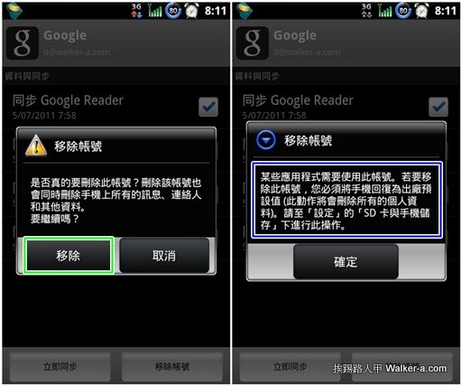
▼Gmail內的移除帳號是針對非第一個登入帳號才能刪除,若強制移除會出現如右圖藍色框內的訊息,此訊息竟告訴使用者到「設定」\「SD卡與手機儲存」\「恢復原廠設定」,天啊!那裡面安裝的軟體豈不是要重來嗎?簡直是晴天霹靂~~~~~,若你的手機有Root,可透過Titanium Backup來備份應用程式後,待回到原廠設定後,此時可以登入想更換的Gmail帳號,接下來再還原之的備份的應用程式。

tb15.jpg


方法二 :


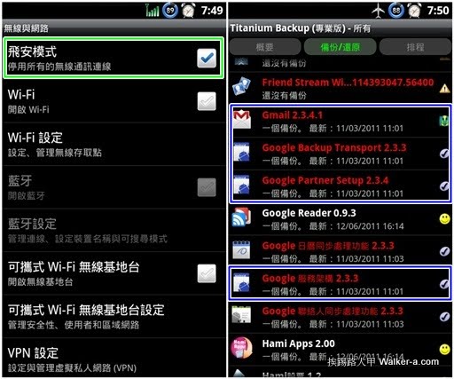
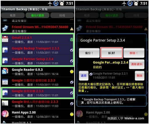
▼首先將手機設定成「飛安模式」,利用Titanium Backup(鈦備份)來凍結Gmail相關程式,有Gmail、Google Backup Transport、Google Partner Setup與Google 服務架構等(藍色框內的程式)。

tb16.jpg

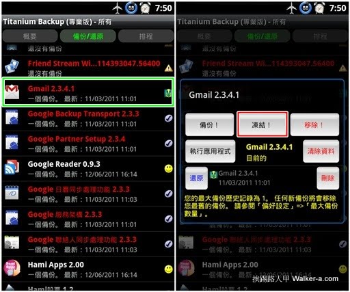
▼點選在想要凍結的程式(綠色框),右圖出現的畫面上點選紅色框內的「凍結」即可,將Gmail、Google Backup Transport、Google Partner Setup與Google 服務架構都凍結。

tb19.jpg

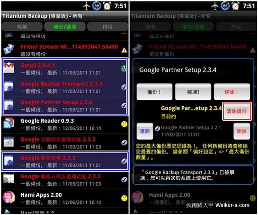
▼被凍結的程式會出現藍紫的背景色,接著再點選每個凍結的程式,結果畫面出現可解凍的圖示,代表此程式目前是被凍結中,按下紅色框內的「清除資料」,一樣必須將Gmail、Google Backup Transport、Google Partner Setup與Google 服務架構等程式內的歷史資料都清除,。

tb17.jpg

▼清除歷史資料都後,記得得幫剛凍結的程式解凍,不然是無法使用的,一一的點選綠色框內的程式,並在右圖中按下紅色框內的「解凍」即可,全部解凍後重新開機。

tb20.jpg

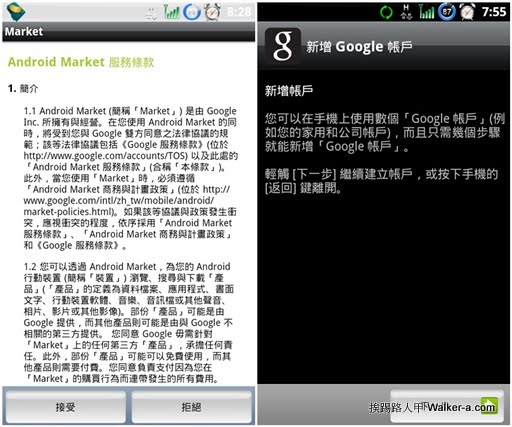
▼重新開機後將「飛航模式」取消,並進入Market或Gmail來重新設定第一個Gmail帳號,果然出現新增帳號的畫面。

tb18.jpg

在 iOS device 同步 google 連絡人


設定 ->電子郵件/通訊錄/行事曆->新增帳號


選 Microsoft Exchange

  電子郵件:填你的Gamil

  域名:空白

  用戶名:填你Gmail address


  密碼:Gmail密碼


  伺服器: m.google.com

2011年11月10日 星期四

監看網路封包程式設計概說


作者: 邵文琳

前一個禮拜花了不少時間在看網路封包方面的程式設計 ..覺得十分有興趣.
感謝charles 和 ellery 的幫助 . 讓我觀念比較清楚 ...
在這裡我把我這一個星期的學習心得寫下來.
讓大家以後若有機會寫到類似程式時, 可是事半功倍 ..
網路程式設計方面相關資料很多 . 但是都是對比較上層的tcp,或udp的應用在做介紹.
對於網路層和datalink層面則著墨較少 .
所以"對我而言" 學習起來比較困難. 希望寫下這個對大家會有幫助.

一個網路封包監看程式 . 說穿了 只有四個重點:

第一 . 開啟一個可接收raw packet 的socket .
一般我們開始socket接收tcp或udp的packet 時, 我們收到的內容就直接是資料內容 .
kernel 己經幫我們把ethernet header 和 ip 或 arp header 都拿掉了.
但是在寫網路封包程式時, 我們需要header . 因此我們在開啟socket 的時候,就可以針對我們要收集的封包總類做過濾. 要求接收到的資料裡要包涵完整的封包標頭檔...

第二 . 有條件的接收封包和無條件的接收封包.
網路卡只會接收到ethernet header 的target mac 是自己的mac 時, 或接收到TARGET MAC 為 ff:ff:ff:ff:ff 的封包, 或是multicasting 的封包(也就是target ip是224開頭的封包 . 這種情況叫做 nonPromiscuous . 當我們要監看網路封包時,希望收到的不只是broadcast 或是 multicasting 或是自己的封包時, 我就要把網路卡設定成 Promiscuous . 如此一來我們就可以接到實體網路上的所有封包了...

第三 . filter 的設定.
當我們把網路卡設成 Promiscuous , 而且看到了所有封包header 時, 我們就可以依照我們自己的意思去過濾出我們想要的封包 . 可是一個問題來了 .. 網路上的封包那麼多.我們全都要一個個的去把它的標頭打開, 看看是不是自己要看的封包. 這樣做花的時間太長.以致於後面進來的封包都塞在buffer 裡, 等你一個個的檢查..我們需要一個filter 建立在硬體層和聯結層中建立一個filter , 先過濾出我們要的封包,再交由程式處理 . 這就是filter的功用.這種filter 是由bpf code 寫出來的! 不會寫bpf code ? 沒關係. 我們還是有別的方法把它變出來 ,,,,,

第四 . multiplexing I/O (blocking VS noblocking)
就如我們所知道的當我們在receving packet 時. 如果沒有資料進來, 程式就會等在那裡 ,這種情況叫做blocking , 但是有時候我們不想要無止限的等在那裡時, 郤又沒法把break 出來時,怎麼辦呢?使用signal 嗎? 另一種解決方式就是把資料流做unblocking.但unblocking 郤不能完成解決我的需求, 於是我利用到了 multiplexing I/O.接下來我在對以上四項做詳細解釋和範例:

第一 socket .
要如何開一個可以接收raw_data 的socket呢 ?

int sock;

// 開一個接收所有走ip protocol 封包的完整封包
sock = socket(PF_PACKET, SOCK_RAW, htons(ETH_P_IP));

// 開一個接收所有走arp protocol 封包的完整封包
sock = socket(PF_PACKET, SOCK_RAW, htons(ETH_P_ARP));

// 開一個接收所有 protocol 封包的完整封包
sock = socket(PF_PACKET, SOCK_RAW, htons(ETH_P_All));

// 在linux 下接收datalink 層的網路封包
sock = socket(PF_INET, SOCK_PACKET, htons(ETH+P_ALL));


PF_PACKET 支援兩個socket type:SOCK_RAW 和 SOCK_DGRAM, SOCK_RAW 會留下完整的 ethernet 標頭.SOCK_DGRAM 會去掉ETHERNET 標頭.但在linux 下使用PF_SOCK , SOCK_RAW 會有問題.最好是使用 PF_INET, SOCKET_PACKET 也可以留下完整的實體層的標頭.

第二 Promiscuous.
網路卡預設當然都是nonPromiscuous , 要變成 Promiscuous 必須對網卡做設定.在socket 己經open 下

#include
#include
struct ifreq ifrq;

strncpy(ethreq.ifr_name,"eth0",IFNAMSIZ);
ioctl(sock,SIOCGIFFLAGS,&ifrq);
ifrq.ifr_flags|=IFF_PROMISC;
ioctl(sock,SIOCSIFFLAGS,&ifrq);

若在打開之後,沒有在程式結束前關閉. 它就會一直打開哦 . 所以記得要關閉它.


strncpy(ethreq.ifr_name,"eth0",IFNAMSIZ);
ioctl(sock,SIOCGIFFLAGS,&ifrq);
ifrq.ifr_flags&=~IFF_PROMISC;
ioctl(sock,SIOCSIFFLAGS,&ifrq);


第三. 設filter
filter 的設定主要是使用在實體層和連接層中間 . 用一種近似組語的bpf code 組成.寫起來挺麻煩的 . 所以我們直接使用tcpdump -dd 來產生的binary code 來用 .

for example:
tcpdump -dd ip dst 172.16.0.3
{ 0x28, 0, 0, 0x0000000c },
{ 0x15, 0, 3, 0x00000800 },
{ 0x20, 0, 0, 0x0000001e },
{ 0x15, 0, 1, 0xac100003 },
{ 0x6, 0, 0, 0x00000044 },
{ 0x6, 0, 0, 0x00000000 },
tcpdump -dd ip src 172.16.0.3
{ 0x28, 0, 0, 0x0000000c },
{ 0x15, 0, 3, 0x00000800 },
{ 0x20, 0, 0, 0x0000001a },
{ 0x15, 0, 1, 0xac100003 },
{ 0x6, 0, 0, 0x00000044 },
{ 0x6, 0, 0, 0x00000000 },
tcpdump -dd arp dst 172.16.0.3
{ 0x28, 0, 0, 0x0000000c },
{ 0x15, 0, 3, 0x00000806 },
{ 0x2 0, 0, 0, 0x00000026 },
{ 0x15, 0, 1, 0xac100003 },
{ 0x6, 0, 0, 0x00000044 },
{ 0x6, 0, 0, 0x00000000 },

其實這些code 的產生是有跡可找的..我就把下面程式碼的binary code 原始bpf pesude code 列出來,可以相對應比較看看

/*
udp and host 192.168.9.10 and src port 5000
(000) ldh [12]
(001) jeq #0x800 jt 2 jf 14
(002) ldb [23]
(003) jeq #0x11 jt 4 jf 14
(004) ld [26]
(005) jeq #0xc0a8090a jt 8 jf 6
(006) ld [30]
(007) jeq #0xc0a8090a jt 8 jf 14
(008) ldh [20]
(009) jset #0x1fff jt 14 jf 10
(010) ldxb 4*([14]&0xf)
(011) ldh [x + 14]
(012) jeq #0x1388 jt 13 jf 14
(013) ret #68
(014) ret #0
*/


我們可以依我們的需要去下command 給tcpdump -dd 幫我們產生binary code. tcpdump, 不但區分不同的protocol. 來源,目的地, even 標頭的第幾個byte,和要接收封包的大小, 都可以變化. 實在是太神奇了.

接下來我們要把code 整合到程式裡去 ...

第四 . blocking VS noblocking multiplexing I/O
unblocking 最重要的意思是當有資料流進來時立刻就傳回. 當沒有資料流進來時, 也傳回0.於是我們就可以利用unblocking 和loop 來控制我們要的時間.
以下是程式的寫法:

(fcntl(fd ,F_GETFL) & O_NONBLOCKING) // 1 成功 0 失敗


但是把資料一點一滴的傳進來也並不是我們要的 . 我們還是希望傳進來的資料是一個個block 過的資料,只是當沒有資料進來時, 能夠不要永遠的等在那而己.這就是multiplexing I/O 的概念.當我們read 和recvfrom 一個 file handle 時, 我們可以設定如何沒有資料進來時我要等多久,就能回到程式繼續執行我們要做的動作.
以下是程式的寫法:

#include "sys/time.h"
#include "sys/select.h"

int sock;
struct timeval tv;
fd_set readfds;

sock = socket(...);
tv.tv_sec=1;
tv.tv_usec=0;
FD_ZERO(&readfds); // 清空file handle set.
FD_SET(sock,&readfds); // 加入一個file handle 到file handle set
FD_SET(xxx,&readfds); // 如果還有別的file handle 也要加入同一個
set做控制的話 ..
select(sock+1,&readfds,NULL,NULL,&tv); // 對 file handle set 設
定時間控制
if(FD_ISSET(sock,&readfds)){ // 依readfds的設定來看是否為
true , 依我們的
例出來說,程式會在這裡等上一秒鐘. 如果在這一秒裡有data流進來,
傳回true, 再交給recvfrom把data 接下來, 否則一秒鐘後傳回false
!
// recvfrom(....)
}


基本上把握這幾個主要的重點, 要變化出自己的sniffer 不是問題..剩下來比較討厭的就是把ip 轉成network address to host address..大小印地安,和 inetaddr, inet_addr, inet_aton, inet_ntoa ...這些變來變去的死東西了.

2011年11月3日 星期四

Wireshark 遠端抓取封包功能


在Wireshark較新版本中新增了遠端抓取封包功能,至於遠端抓取封包的好處自然不用說了,可以實現跨地域、彌補缺乏技術支援等等。
本文的主要目的是Demo,如何使用Wireshark進行遠端抓取封包,以及抓取封包中使用到部分技術原理說明。
需要說明的是,WIRESHARK 之所以能夠遠端抓取封包,是因為在安裝WinPcap時,已經Default安裝了一個名為rpcapd的遠端抓取封包程式,位置在\Program Files\WinPcap>。
在本地和遠程機器都安裝完畢WS後,就可以開始遠端抓取封包了。
本例中,2台測試機IP分別是:192.168.10.2(local)和192.168.10.5(remote)。
  • 啟動遠端設備rpcapd
在遠端機器中,執行C:\Program Files\WinPcap>rpcapd.exe -n,如下圖
提示service已執行。其中,參數-n的意思是不驗證權限既可連接,更多rpcapd資訊請參照文後所附。
  • 連接遠端抓取封包程式
啟動local WIRESHARK,在Capture選項欄選擇Remote,跳出新窗口,要求輸入IP地址、端口及驗證訊息。
由於遠端機器無驗證要求,即匿名可連接,直接輸入IP 192.168.10.3,Port使用2002
 
  • 選擇遠端抓取封包網卡
成功連接後,Interface處會顯示遠端IP地址信息。
由於當前機器內通常會有多個網卡,這裡需要選擇正確的capture網卡。
  • 抓取封包
以上設置完成後,就可以抓取封包了。
心細的你,可能發現了一些可選設置的地方,即Remote Settings。如果沒有特殊要求或想追求性能的話,建議不要修改其中選擇。
接下來,“Start”即可。
 上圖是遠端抓取封包的測試內容。
另外,從WIRESHARK Title中亦可看出,當前正在遠端抓取封包。
附:rpcapd參數
USAGE:
rpcapd [-b] [-p ] [-6] [-l ] [-a ]
[-n] [-v] [-d] [ -s ] [-f ]
-b
: the address to bind to (either numeric or literal).
Default: it binds to all local IPv4 addresses
-p : the port to bind to. Default: it binds to port 2002
-4: use only IPv4 (default both IPv4 and IPv6 waiting sockets are used)
-l : a file that keeps the list of the hosts which are allowed
to connect to this server ( if more than one, list them one per line).
We suggest to use literal names (instead of numeric ones) in order to
avoid problems with different address families
-n: permit NULL authentication (usually used with '-l')
-a : run in active mode when connecting to 'host' on port 'port'
In case 'port' is omitted, the default port (2003) is used
-v: run in active mode only (default: if ' -a' is specified, it accepts
passive connections as well
-d: run in daemon mode (UNIX only) or as a service (Win32 only)
Warning (Win32): this switch is provided automatically when the service
is started from the control panel
-s : save the current configuration to file
-f : load the current configuration from file; all the switches
specified from the command line are ignored
-h: print this help screen

How to repair and clone disk with ddrescue

  ddrescue  is a tool that can be used to repair and clone disks on a  Linux system . This includes hard drives, partitions, DVD discs, flas...